Additional steps for creating a MM3 modchip
and how I broke my PS1
This page documents some additional steps I used to program a MM3 modchip, which I then proceeded to try and install in my PS1, only for me to break it.
Additional steps for creating a MM3 modchip
I was following this excellent guide by William Quade on how to install the “MM3” modchip.
Unfortunately it ends with this statement:
I’ll have a tutorial on how to program these PIC chips in the future.
The oldest comment seems to be from 2018, so I am not certain if this guide is coming. So, since I’m figuring this out anyways, I figured I’d write up the steps I followed here. Most of my experience is with Arduino, which obscures some of the details of flashing away from the user for simplicity.
I actually first heard about this method from this MattKC video. I never owned this console originally, and was fine with emulation most of the time.
When rewatching this video, I missed the point about there also being an Arduino-based modchip “PsNee”. I actually only noticed this after I already bought a PIC. Oh well, I guess this is an excuse to learn how to program PIC. Maybe I’ll use it if this doesn’t work.
1. Get the parts
From the original blog post, I purchased the following:
| Item | Description |
|---|---|
| Used PS1 | Bought one claimed to be working on Ebay. Really could use a clean when I’m done. It has a SCPH-9000 board. |
| PIC12F629 SOIC-8 | Opted for the SOIC-8 package for this chip, because it was smaller. |
| SOIC-8 breakout board | I had a few SOIC-14 breakout boards already lying around, and what’s a SOIC-8 but a SOIC-14 minus 6? |
| PICkit 3 Programmer | Bought a knockoff from AliExpress. |
2. Program it
I first soldered the PIC chip to my SOIC-8 breakout board, and put it on a breadboard.
I then connected the PIC programmer to the PIC chip based on this datasheet and the breakout for the PICkit 3.
This is the part which was missing from other guides and the video I checked earlier. Probably because it’s not exciting and assumed knowledge.
The .hex for the region of PS1 and PIC chip I was using was available from William Quade’s blog.
The steps that didn’t work
I downloaded PICPgm and the .hex for the region and type of PIC chip I was using
When I launched PICPgm, I saw this error in the Log when trying to “Autodetect Programmer” (and then “Autodetect PIC”):
Autodetecting Programmer ...
Warning: Unable to open parallel port I/O driver!
Installing driver requires admin/root rights.
No Programmer found! Check connection!
No PIC detected!
Re-running as Admin didn’t prompt it to install any drivers. The Power and Active lights on the programmer were on, so that seems to be fine.
Also, I found this when hunting around for drivers:
The PICkit 3 is not recommended for new designs and no new device support will be added to it as of June 1, 2019.
Sounds about right.
Since I was having what seemed to be driver issues, I tried downloading the MPLAB X IDE software, to see if that would fix it.
After installing MPLAB and drivers, PICPgm still couldn’t detect it. I also tried another USB port just in case that was the cause. I did not install any compilers, because I already have the compiled .hex file.
When I used MPLAB to create a “prebuilt” project, the PICkit 3 was not listed as a compatible hardware tool. I tried selecting the PICkit 4 to see if that would work.
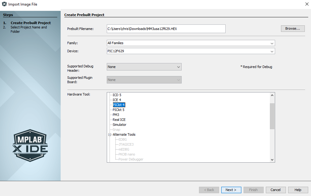
So this didn’t seem to work, because the PICkit 3 was not compatible.
The steps that did work
I think.
I found this page https://microchipdeveloper.com/pickit3:scripttool which had a link to the archive for the PICKit 3 software. My browser complained about this because it was downloading over plain HTTP.
- Download Pickit 3
- Restart computer
-
Pickit 3 will recognize it, but it’s in “MPLAB mode”. The download came with some other firmware, and so I am guessing I have to use that to reconfigure the pickit.
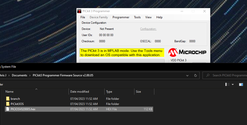
Once I updated the firmware for the pickit 3, it then showed as connected.
- Plug in the header to the pickit.
-
Run a “blank check” to ensure the pickit can actually reach the PIC.
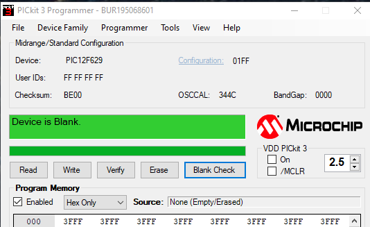
- File -> Import Hex for the MM3 file.
- Click the write button. I’m ignored the Vdd warning about bulk erase operations.
Then I got a programming failed error.
- Actually this Vdd bulk erase operation was important. I set this to 5 and “on”, when the default was off and 2.5V.
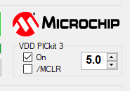
this chip is not connected to anything and so it’s fine that we do this
- then could verify, and this said verification successful.
Cool, this PIC is now an mm3. time to install it
3. Attempt to install the MM3 chip
I have a PU-23 board, and so I used this guide for it
Unfortunately, I thought I could get away with using 22 AWG Solid core wire. This is massively too thick for this purpose.
I ripped up one of the traces on a surface-mount component when trying to install it.
In the current day, maybe emulation on a playstation classic isn’t so bad after all (really easy to modify, native HDMI out, and new hardware).