Binary Keyboard Build Log
A keyboard that types in binary with only two buttons.
View Chris-Johnston/BinaryKeyboard on GitHub
Background
After building the Ergodox keyboard a few months prior, I wanted to make something that was the complete opposite in every way. I also wanted a different project from Internet Xmas Tree and Patio Lights that didn’t involve NeoPixels.
Binary keyboards have been done before. My goal was not to replicate these other projects, but instead to try and create the most ridiculous keyboard I could.
Judging from the reception I received from others both online and in person, I think I accomplished this.
Reception
My goal was to make a working version of this project for a makerfest my school was hosting. I stayed up all night finishing up this version of the keyboard, as well as uploading my source code, pictures, and GIFs to the GitHub repo. While I was up, I thought it would be fun to upload one of those gifs to /r/MechanicalKeyboards.
And then this happened.

I might have been checking my phone constantly for the 48 hours following that.
I found that most of the comments were one of a few things (in no particular order):
- Suggesting the keyboard’s use for the game Osu!
- Suggesting I play Dark Souls with it.
- Questioning why I typed from least significant bit to most significant bit. (I added the option to pick in this commit.)
- Suggesting that I make a Morse code keyboard with 1 button. (I thought about that, but I feel like getting the timings down would be tricky.)
- Or just interesting ASCII art.
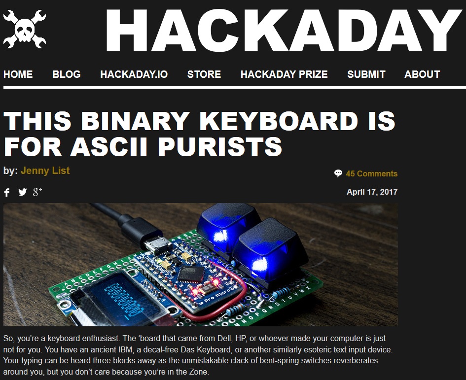
And then it got featured on Hackaday.
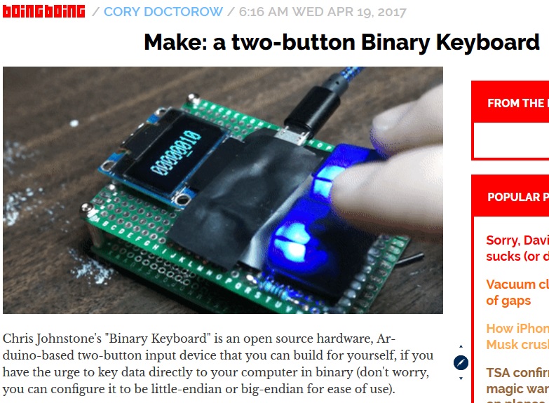
And BoingBoing.
Chris Johnstone
Johnston, not ‘Johnstone’. But cool regardless.
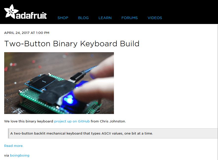
Neat, Adafruit!
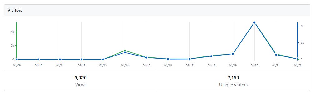
In addition, it got featured at a bunch of other places. What I find funny is that the majority of the traffic came from ycombinator.com (Hacker News), a website I’ve never visited myself (before this). That initial blip on the GitHub traffic graph was from the inital Reddit post, the rest is the aftershock of it.
By far the most rewarding part of this experience is the feedback. Some people love it, some are contributing and suggesting changes and improvements, and a few sound like they are going to build their own which is cool. (If you build your own, please show me pictures.)
The Build
I first created a prototype of this back in early January.
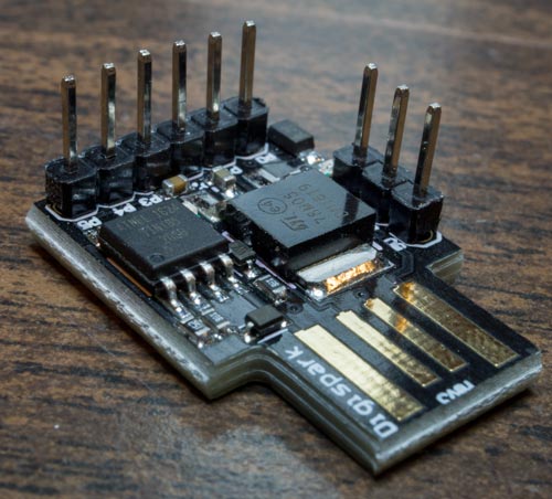
Initially I was planning on using a Digispark, however I found that it didn’t have enough I/O and memory (only 6K!) to do what I wanted.
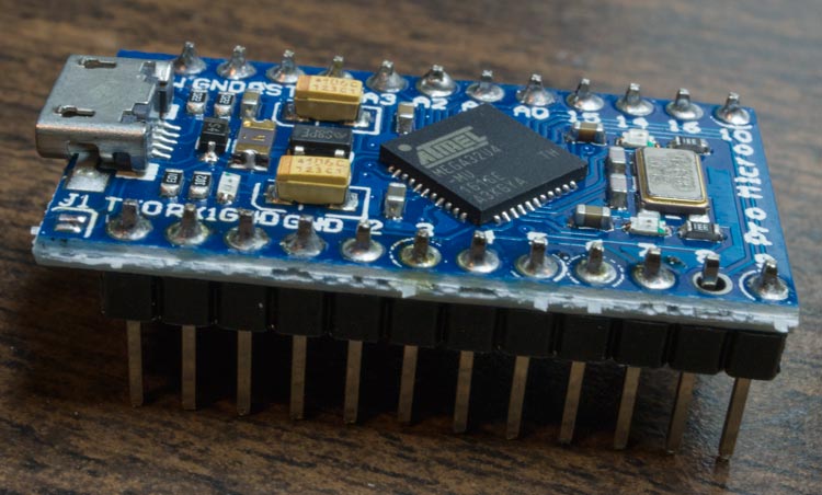
Instead, I used a $3 Arduino Pro Micro knockoff from AliExpress.
Disclaimer: Most of my WIP images are from Snapchat. I only happened to have my phone on me.
A lot of the stuff in the end result is found here, the two buttons (in this case jumper wires), a screen showing binary values, same components.
The next step was to make this a more reliable solution, so I made it on some pegboard with some parts I had lying around.
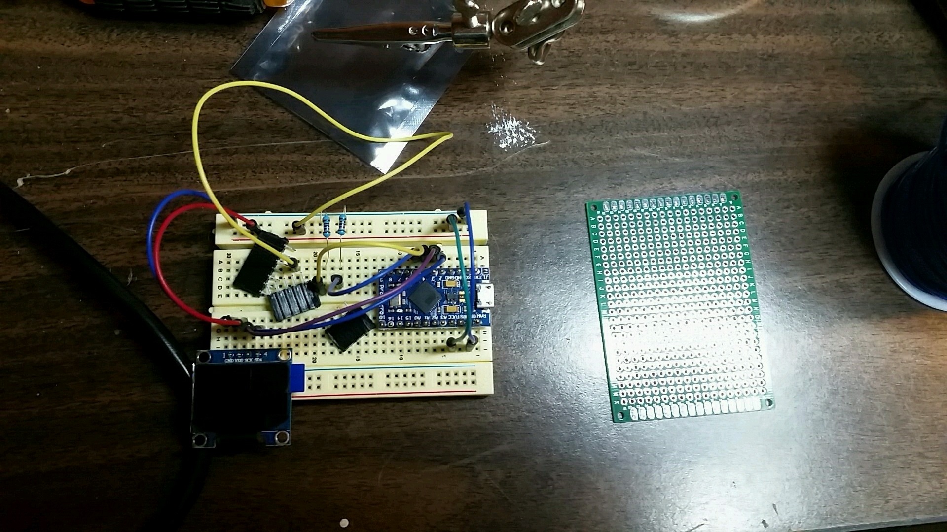
A bit of soldering later…
… and it worked on the first try!
Fast forward a few months.
By this point I had made a schematic & board layout in Eagle, and my next step was to make the circuitboard. (Board layout will be added to repo once I can verify one that works.)
The initial plan was to use my school’s CNC machines to engrave away the copper traces on a copper board, but we couldn’t figure out how to get that working. If anyone reading has an Inventables Carvey and has done this, please contact me.
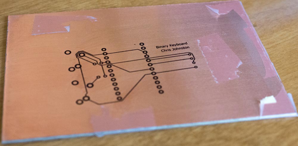
Failing to get the CNC machine to work, I opted to etch the copper board using chemicals (Ferric Chloride). I used resist paper which made the task really easy, all I had to do was run it through a laminator a few times.
On the second time I used less tape. Also I found to ensure printing in B&W, and not greyscale. Greyscale will mess with the thickness of traces.
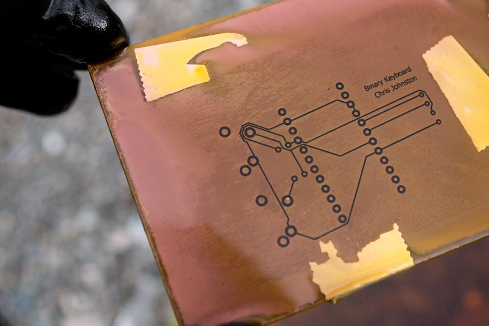
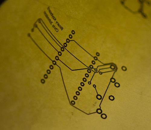
And after some time…
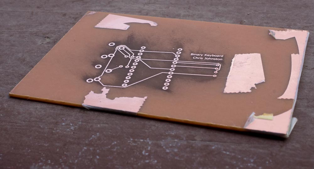
I removed the resist using acetone. I think some of the resist caused that smudge, which is weird because this didn’t happen on my duplicate board. Oh well.
And now is when I noticed a problem with this circuit design.
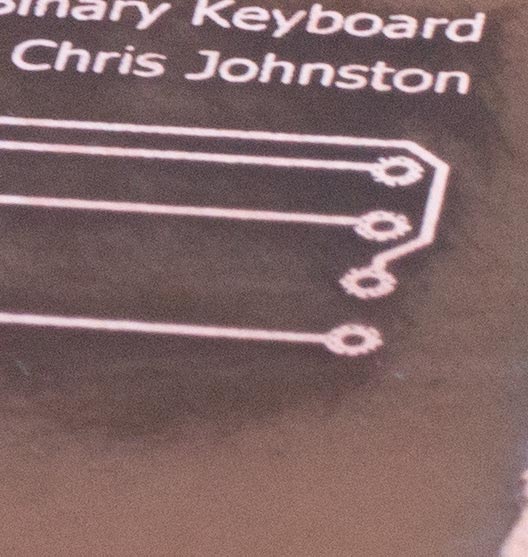
A lot of these traces are too small, and the holes are also too small. Beginner mistake I suppose. Because of this, I wasn’t able to use this board.
I ran out of time to make a circuitboard from scratch for the makerfest that upcoming friday, so I had to stick with a pegboard.
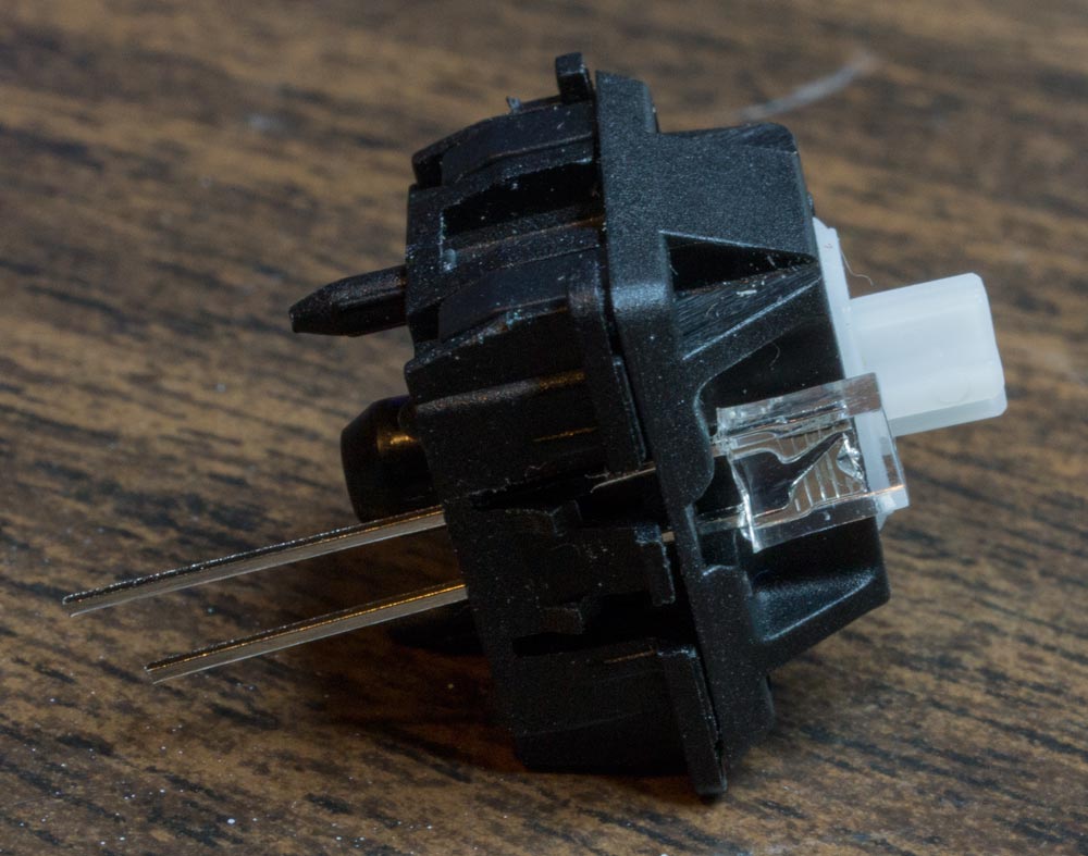
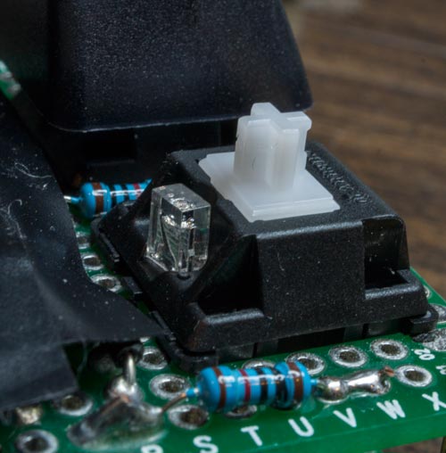
I was able to copy the outline of the Cherry MX switch from bishboria/ErgoDox ‘s acrylic case design. Using that, and with some help from people in the Makerspace, we were able to use the CNC to cut out this shape from the pegboard.
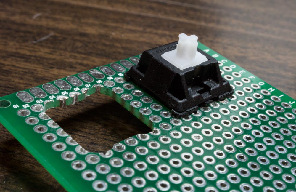
Now I could insert the MX switch in this hole, and it would snap securely in place. I made another prototype, and while I was at it, added backlighting.
I like how Cherry MX switches have space for LEDs. Now I just need to figure out a solution for RGB as many have requested.
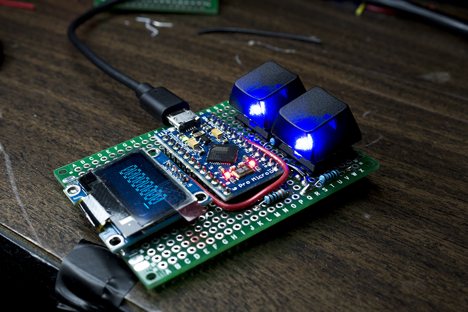
I don’t think anyone picked up on it, but the screen is displaying upside down in this photo. I took this right after I finished the build, but before I had the chance to actually go in and clean up and re-work a lot of the code.
The night before the makerfest, I was able to finalize the software side of things. I don’t really have many pictures to show, it was mostly code cleanup, adding functions for backlighting, and flipping the screen around.
Live Demo
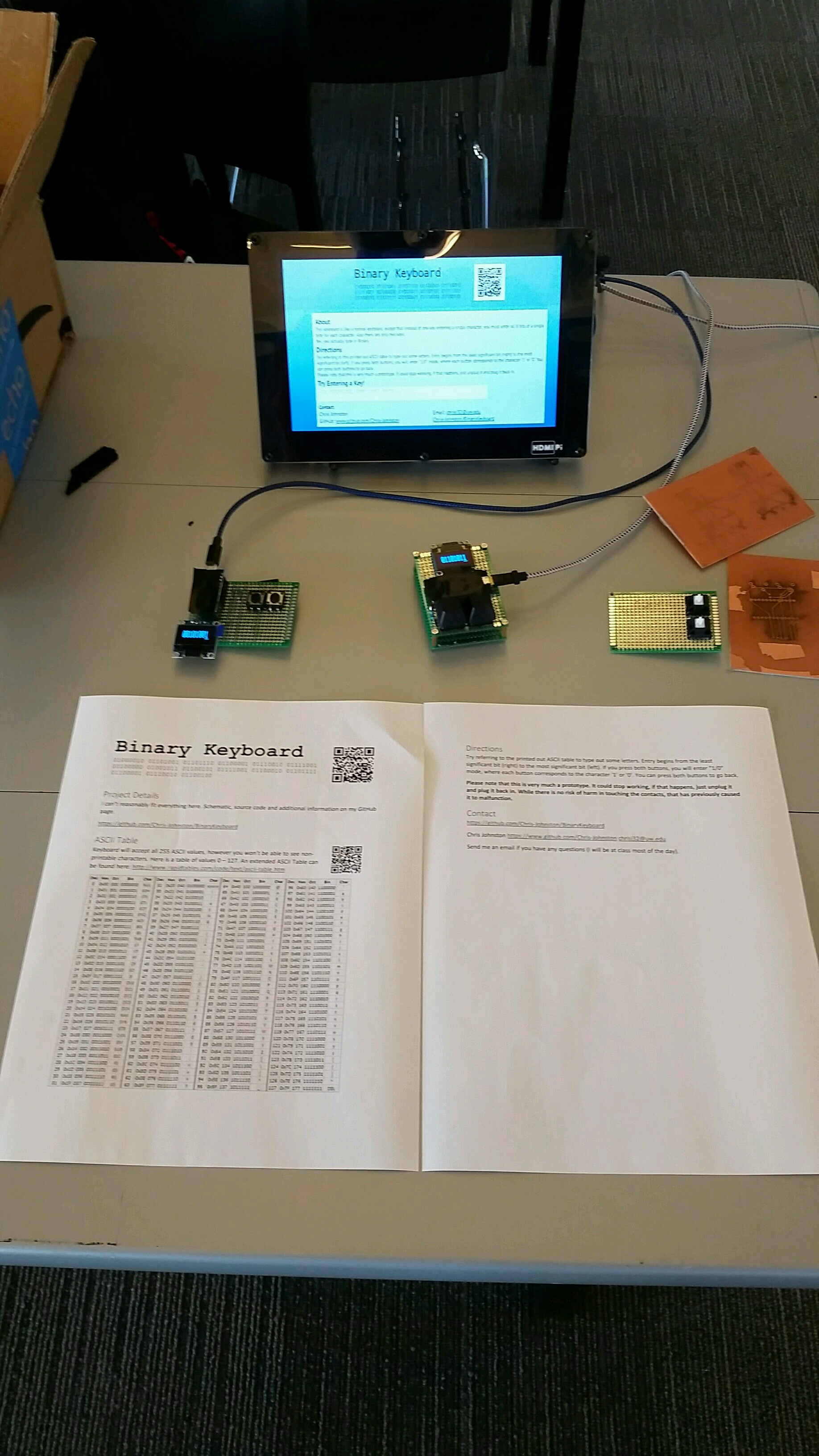
I made a demo kiosk using an Raspberry Pi and an HDMI screen. It would just boot up into the desktop environment and load Chromium in ‘kiosk’ mode to the webpage. It was really laggy and didn’t work great, but it at least provided testers a place to type. I made sure to print out some ASCII tables as well so that people could properly use it.
//todo
I’m not sure what my plans are for continuing this. Ideally, I would like to be able to manufacture some of these circuitboards, and maybe share them around with others.